SENSY LOAD CELLS, SIL READY - EN62061 & EN61508
What’s the standard SIL - 62061 & 61508 (Safety of Machinery) ?
Our modern and industrialised world can no longer operate without machines. Whether they are used for heavy tasks or the most thorough, machines and automated systems are essential tools to reduce employees’ workloads while ensuring speed and quality of work.
As powerful as these tools are, they also present a significant danger for humans. This is how the principles of machine safety and machine directive were born.
The idea of different safety standards is to provide legal certainty for both the manufacturer and the user, the latter wishing to have access to a safe and efficient machine.
Using this approach, all machine manufacturers must make risk assessments in order to eliminate or reduce them according to requirements. This is very important when we refer to the features of safety itself.
One of the most commonly used safety standards is EN / IEC 61508 – ‘Functional Safety of Electrical, Electronic and Programmable Electronic Safety-related Systems’. This standard gives valuable information on producing a control system.
SENSY, as a partner in your process of creating and securing your machines, offers solutions for producing SIL-compliant installations up to SIL3.
Within this perspective, this article offers a summary of the main concepts to keep in mind when carrying out a security order.
Determine your required SIL
IEC 61508 provides different levels of safety in machines. These safety integrating levels (SIL) are represented by a number from "1" to "4", with "SIL1" being the lowest level and "SIL4" the highest.
The requirements for developing systems at different levels can vary greatly in cost. Thus, it is important to choose the SIL level your installation needs.
Determination of the required SIL level depends on four variables: the severity of the injuries (Se), the CI which is the sum of the levels of the exposure frequency to the hazard (Fr), the probability of accident (Pr) and the probability of avoiding the danger or limiting the damages (Av).
To determine these values, you can use the tables below.
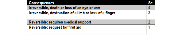
The first table is used to determine the value of injury severity (Se).
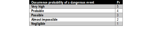
The three tables below determine the factors upon which the CI coefficient will depend. In general, CI is defined as the sum of three factors: the frequency of exposure, the probability of hazard occurrence, and the probability of damages.


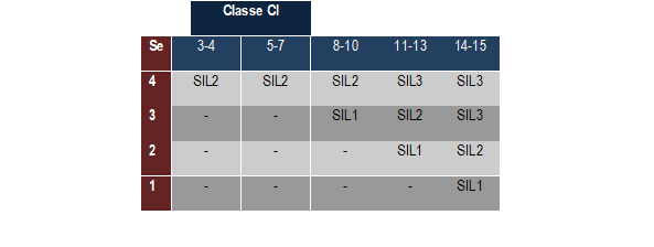
Once the CIs and Se have been obtained, they can be integrated into the table below to quickly get an idea of the minimum SIL to be reached.
Design of safety function
The creation of a system providing a safety function requires the estimation of several factors:
- The architecture of different hardware and software (categories);
- Possible diagnostic coverage;
- Component reliability (λ);
- And the common causes of failures depending on the architecture.
Composition of a safety function
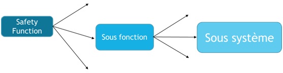
In the case of a sensor, this is not a subsystem itself, but an element of the subsystem, which means it is essential to validate the entire subsystem.
Does the sensor work alone? Does the sensor work in redundant pairs? Should tests be performed during operation? These are all issues that must be taken into consideration when deciding to create a subsystem.
For example, consider the safety function responsible for detecting a limit switch and cutting out a motor.
In general, the system can be divided into three functional blocks: detection, logic and output.
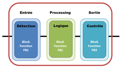
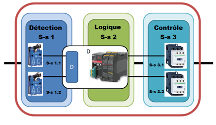
To fulfill this function, various elements will be added to guarantee the different functionalities. In this case, there would be two switches to guarantee the detection part, a programmable logic controller and a pair of relays, in series, to shut down the motor.
In this case, the switches are only part of the ‘detection’ function block. It is acknowledged that the relay is an element of the subsystem (which is also the case of sensors).
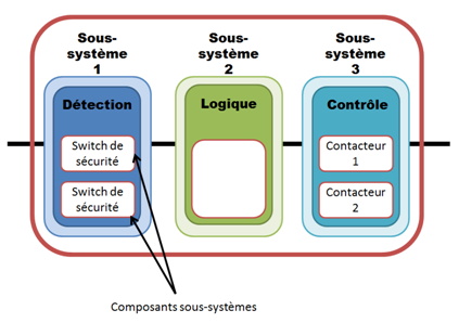
Note that the relays are not sufficient to guarantee detection security. The PLC also has a role to play. In this case, it could test the presence of sensors and check for short circuits.
Subsystem architecture
The different types of architecture are illustrated below. Each type has its own way of calculating failure probabilities. To save space, we have not detailed these different ways but advise that you consult the standard for further information.
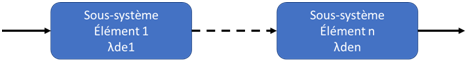
Type A
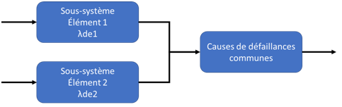
Type B
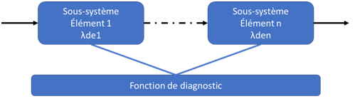
Type C
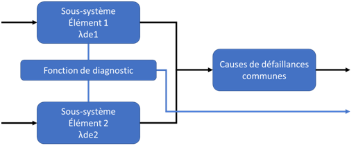
Type D
Component reliability (λd)
The reliability of components is obviously at the heart of a system's ability to perform its security function. The lower the reliability of a component, the more likely it is to cause failures (and thus dangerous failures).
Within the SIL framework, the reliability of the components is entered directly into the calculation of the PFHd (probability of failure per hours - dangerous) and is applied according to the architecture.
Note, however, that it would be wrong to consider a component’s reliability as the sole justification for achieving high performance levels.
Diagnostic coverage
Diagnostic coverage is the value that quantifies the system's ability to diagnose dangerous faults. This value is expressed as a percentage.
For example, the diagnostic coverage of a relay fault can be assessed. If a N / O relay were to close on an open circuit, the system would not necessarily be able to differentiate between the fault and the conventional opening. A highly diagnostic system will include other systems which enable the state of the relay to be checked.
It is obvious that the system’s architecture has a direct link to the diagnostic coverage of the latter.
In general, this is seen as the difference in the number of dangerous failures detected by the total number of dangerous failures:
It is also important to note that some architectures are not appropriate to justify the SIL level of some systems. Thus, a category 2 system is readily suitable for a simple detection system (i.e. mechanical stops) which can easily be tested during activation of the machine. However, the reliability of more complex systems would be very bad. These systems may require extremely complicated test systems. Therefore, it is often easier and more economical to test a system with a redundant architecture.
Common causes of failure
The common causes of failures must also be considered. Indeed, in these systems, possible causes of failure may affect several of the system’s elements (i.e. both channels can be overloaded at the same time!).
The causes of common failures can be estimated on the basis of IEC 61508, although it is still possible to be satisfied with the maximum ‘default’ value of 10%. It is obvious that common causes of failures only occur in the presence of a system with two input and/or output signals.
The common failure rate is given in percentage.
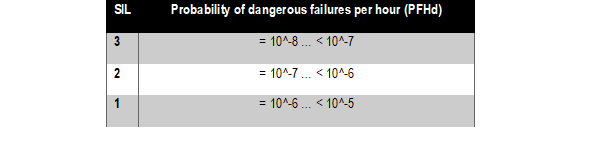
Determining if the SIL level has been reached
All these factors make it possible, using the standard, to determine a PFHd coefficient achieved. For more details, refer to the corresponding standard.
A quick glance at the table below enables a check to see if the required SIL has been reached: