
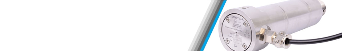
SPECIALIZED IN THE MANUFACTURING OF CUSTOM-MADE LOAD PINS
Why choose a load pin?
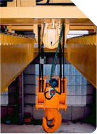
Load pins are used for force, load and constraint measurement in a wide range of applications and environments (industrial, aeronautical, marine or submarine when fully submerged at sea).
As a result of their design and robustness, they are often favoured for measuring and preventing overloads. Indeed, integrated in a load limitation system, they make it possible to assure the safety functions of any type of lifting device (crane, lift, construction crane, harbour crane, arial platform, etc.).
On a daily basis, we develop custom-made load pins for very different applications; here are some examples:


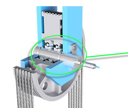
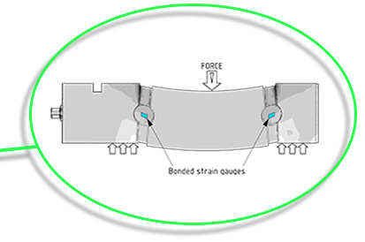
Load pin operation
 |  |
The variety of SENSY’s offer
With more than 30 years of experience in the field of force measurement, SENSY currently offers one of the most complete product ranges on the market.
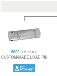
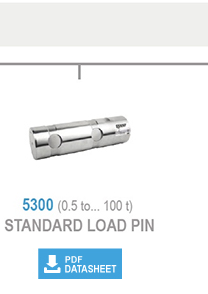
One of the main advantages of the load pin is its mechanical integration. Indeed, even if we have a range of standard instrumented load pins (5300) that can be used for new developments, on a daily basis we develop custom-made load pins (model 5000).
On a machine or on an existing mechanical assembly, and to integrate a load pin in place of the current non-instrumented axis, we machine the piece according to the dimensions provided by our customer and equip it with strain gauges which enable us to obtain an electrical signal proportional to the applied load.
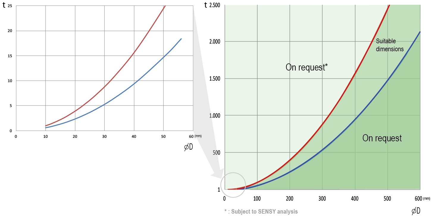
As illustrated below, the diameter can vary from 10 to 600 mm for capacities ranging from 0.5 to 2000 t.
Examples :
 | |
 |
Different variants of load pins depending on the environment
Having specialised in manufacturing load pins since 1985, we have been able to develop real expertise and thus to propose the following variants:
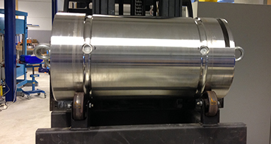
Custom-made load pins
Load pin design and manufacturing according to your mechanical specificities (diameter, capacity, etc.)
Although we offer a range of standard load pins for capacities between 0.5 and 125 t with fixed dimensions, it is possible that they do not match our customers’ needs in terms of capacity (up to 2000 t) and dimensions. It is even more true when we are equipping existing material, for which mechanical modification would be impossible or too costly compared to producing a custom-made clevis pin, even just one piece.
Hazardous-zone load pin
Available certifications : ATEX, IECEx, CSA (for some types of load cells)
Our load pins are used in several applications exposed to zones of variable explosive risks (gas and / or dust). For more than 20 years, we have been awarded ATEX Ex ia IIC T4 and T6 or Exd certification for our load pins and load cells. A few years ago, we have also obtained IECEx Ex ia IIC T6 certification, as well as CSA Canada and US Class 1 Div 1 certification (for some load cell models).
Redundant load pins - Sil load pins
SIL ready (EN 61508), PL ready (EN 13849-1), direction X/Y
Safety is now the priority for everything. SENSY offers a range of sensors that can be used in your EN61508, EN62061 or ISO13849 system. Find out how we can help you build your SIL and PL systems.
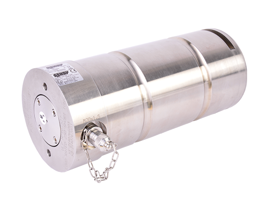
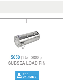
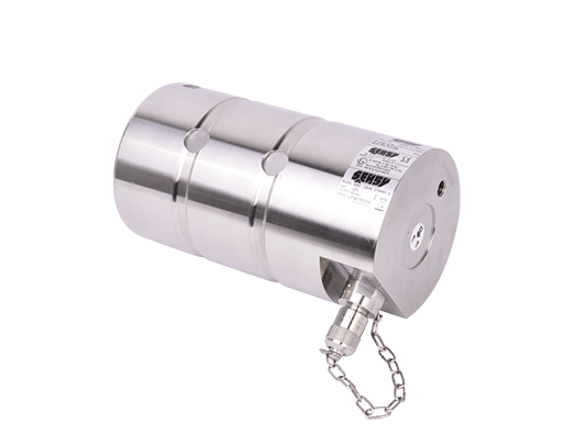
Submersible load pins
Depth: up to -7500 m / -24 606 ft (750 bars / 11 000 psi)
Our standard load pin model (5300) and custom-made models (5000 and 5600) are suitable for Ingress Protection IP65 to 67, with specifics for marine and offshore environments for the IP67 version.
As soon as these Clevis pins are submerged for a longer duration or permanently, any corresponding challenges are addressed with our model 5050. This design is based on internal bonding to reach IP68 protection.
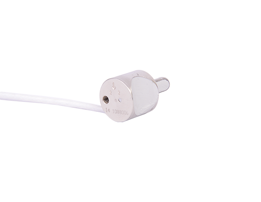
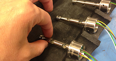
Miniature load pins
Compact, robust and resistant to harsh environments.
Apart from regular load pins in our standard or custom-made product range with the classic pin diameter of between 15 and 450mm (or more) for hoisting systems, mooring winches, test benches and others, new applications, mainly in the aerospace industry for qualification test purpose or on-board controls, require more and more compact instrumented pins, with tiny diameters and very short operating lengths.
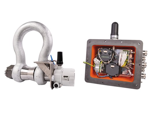
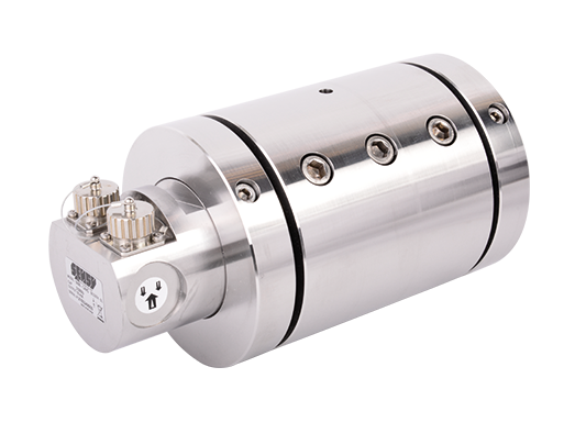
ATEX / CSA Wireless load pin
Instrumented Exi / Exd certified load pin equipped with a transmitter in explosion-proof enclosure, certified to operate in explosive zone.
With our ATEX, IECEx and CSA (CA / US) certifications for most of our sensor models, we are also able to provide wireless solutions for applications in zones 0 and 20 (and therefore also for zones 1, 21, 2 and 22) in combination with an ATEX certified Ex ia IIC T4 / Ex iaD20 IP68 T82 ° C and CSA Class 1 Div 1 transmitter enclosure.
We therefore offer solutions including load pins with an output signal in mV/V, a transmitter in an enclosure + Ex antenna (ingress protection : IP67) and a battery.
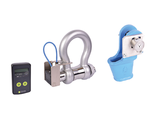
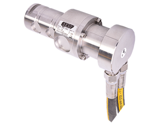
Wireless load shackles / Wireless wedge sockets
Load shackles and wedge sockets also available in wireless version
Our model 5000M – a load shackle comprising a zinc-plated, painted or stainless steel shackle and stainless-steel load pin – and usually supplied in a hard-wired solution, is also available with a wireless system module mounted at the load pin end (5000M-WI), including a transmitter, antenna and battery.
For use in hazardous zones, we can supply solutions for zones 0, 20, 1, 21, 2 and 22 for the load shackle and its transmitter.
CONFIGURATORS AVAILABLES
 CONFIGURATOR CUSTOM LOAD PIN5000
  CONFIGURATOR CUSTOM SUBSEA LOAD PIN5050
  CONFIGURATOR LOAD PIN DESIGN 5000 & 5050