
Poser une question
Electroniques
- Que faire si un BRIDGE-BOY se déclenche de manière intempestive lorsque le levage est à vide?
- Comment changer la plage de sensibilité du BRIDGE-BOY?
- Quelle est la précision de l’INDI-PAXS?
- Peut-on brancher plusieurs capteurs en parallèle sur la même électronique de limitation de charge ?
- Comment tarer un afficheur DIP-Fx-yz à l’aide d’un contact extérieur ?
- Quelle est la précision d’un système de limitation de charge dont le capteur est un axe dynamométrique?
- Comment configurer la sortie RS232 de l'indicateur de pesage INDI5250 et de l'indicateur étalon (INDI-00)?
- Comment définir des seuils de déclenchement différents à partir d'un bouton sur nos limiteurs de charges digitaux?
- Comment configurer les produits de la famille PAX pour récupérer la valeur affichée sur mon PC ou mon automate?
- Comment appliquer une résistance de calibration (Rcal) sur un capteur déjà livré ?
- Quelle est la vitesse de rafraîchissement de nos cartes de communication pour les produits de la famille "PAX"?
I have a load limiter composed of a load cell and a BRIDGE-BOY.
When there is no load on hoisting device, the BRIDGE-BOY triggers unexpectedly.
Answer:
To ensure positive safety, the BRIDGE-BOY will set itself to fault when the output signal falls below -0.5 V.
 Set the hoisting device without any load. Measure the voltage between terminal 8 (+) and GND (-)
(see drawing above).
This signal may not be negative. If necessary increase it to 0 V or a slightly positive value (ex: 0.1 V) by using the zero potentiometer (Z).
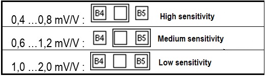
How to change the sensitivity range of the bridge-boy ?
[answer] =>Description
I can’t get the requested output signal using potentiometer S.
How do I change the sensitivity range of the BRIDGE-BOY ?
Answer
By modifying the B4-B5 soldering (see box in red) according to the table at the bottom of the page.

What is the accuracy of the INDI-PAXS ?
[answer] =>Answer:
The accuracy class of the INDI-PAXS indicated by Sensy is ±0.1% of full scale.
In fact this value can be defined more precisely:
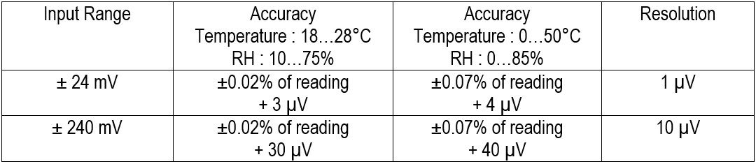
Example: the accuracy of the INDI-PAXS if connected to a sensor providing a signal of 2 mV/V, used between 18 and 28° C (relative humidity between 10 and 75%) and supplied with 10 V, the accuracy will be better than : ± 0.02% ± (3/20000) = ± 0.035% of full scale.However, in a temperature range of 0 to 50 ° C (0 to 85% relative humidity), this becomes: ± 0.07% ± (4/20000) = ± 0.09% of full scale.In these cases, the maximum resolution is 1/20000 = 0.005% of full scale.
Note :
- These values are only valid after a warm-up period of 20 minutes.
- For the temperature range 0-50°C, the thermal drifts are included in the specified accuracies.
- The maximum display refresh rate (dSP-t) is 10/sec. to enable internal zero compensation.
In addition to the above:
- The accuracy of the excitation voltage of the sensor (5 or 10 VDC) is ± 2%.
The maximum temperature drift (ratio metric) is 20 ppm/°C. - The accuracy of the analog output (option CARD-CDL10) is ±0.17% of full scale in the range of 18…28°C and ±0.4% of full scale in the range of 0…50°C.
Is it allowed to connect multiple sensors in parallel to the same overload protection electronics?
[answer] =>Note:
This is a common practice for weighing systems (unamplified mV/V signals).
Answer:
No, because positive safety is no longer guaranteed.Positive safety is the safety function of a load limiter that will trip when load cell/load pin signal is lost, whatever the cause may be.With several sensors connected to one load limiter (BRIDGE-BOY, CRANE-BOY or INDI-BOY), one failed sensor will not be detected and system keeps operating in an unsafe mode
Solutions are:
- Safe parallel connection using a JBOX-LCI Smart Junction Box.Indeed, the JBOX-LCI, beyond providing a summed signal to the load limiter, performs the monitoring of each individual sensor signal.
Remarks:
• Up to 4 sensors.
• The JBOX-LCI is powered by limiting electronics.
• It is usable with CRANE-BOY and INDI-BOY but not with BRIDGE-BOY.
• The impedance of the sensors can be 350 Ω for 2 sensors. It must be 700 or 1,000 Ω for 3 or 4 sensors. - Individual overload protection: each sensor connected to BRIDGE-BOY, CRANE-BOY, etc. and the sum of loads using summing electronics (BRIDGE-BOY (with E-SUM option), CRANE- SUMD and DISP-SUMD).
- For overload protection of 2 force sensors (or load pins) and on the sum of loads, the CRANE-BOYDP and DISP-BOYDP are overload protection electronics with 2 analog inputs.
Note: Input signal in V with option T or in mA with option J or C
How to tare a DIS P-Fx-yz display using an external contact.
[answer] =>Answer:
It is possible to tare a DISP-Fx-yz display using a potential-free external contact.
To do this:
- Make sure that the "Calib'n lock" dipswitch is in the "lock" position (on)
- Make a temporary contact between terminals 7 (Common) and 8 (CC.1), with push button for example.

[meta_title] => [meta_description] => [meta_keywords] => [tags] => [link_rewrite] => How-to-tare-a-DIS-P-Fx-yz-display-using-an-external-contact [link_rewrite_cat] => electronics )[5] => Array ( [id_gomakoil_faq] => 14 [id_gomakoil_faq_category] => 1 [link_rewrite_no] => [most] => 0 [association] => 0 [hide_faq] => 0 [name] => Admin [email] => no [by_customer] => 0 [position] => 13 [active] => 1 [date_add] => 2019-06-13 07:47:04 [as_url] => 0 [id_lang] => 2 [id_shop] => 1 [question] =>
What is the accuracy of an overload protection system for EOT crane using load pins.
[answer] =>The aim of this document is to analyze where the different measurement errors come from and to define their importance.
The measurement accuracy of an overload protection system is dependent of several factors:
- Accuracy of the load-pin
A load pin has essentially mechanical errors (non-linearity, hysteresis and non-repeatability). They depend on the dimensions of the axis (length / diameter ratio which cannot be too small) as well as the quality of the supports.For standard axes (5300 series), this error represents ± 0.5% of their full scale.If necessary, this error can be reduced to ± 0.2% by profiling the axis (feasibility to check).
On the other hand, if the ratio length / diameter is too small this error can go up to 5%.
As the thermal drifts of zero and sensitivity are less than 0.2% of full scale / 10° C, they are often negligible compared to mechanical errors. - Accuracy of the load limitation electronics
The accuracy of a load limitation electronics like Crane-Boy is of the order of ± 0.1%.
The error induced by these electronics is therefore generally negligible compared to other errors - Weight of the hoisting cable
Higher the load smaller is the part of cable supported by the load pin.
The importance of this error depends on the ratio between the cable weight and the nominal load hoisted.
The only way to cancel this error is to always do the measurements at the same height.
To eliminate this error, it will therefore be necessary to measure with the load at the same height or to provide a correction system taking into account the height of this height. - Errors due to frictions in the pulley blocks
The consequence of frictions in the various pulleys is that the apparent load on the load pin seems lighter when the load is being hoisted and heavier when the load is being lowered.
It is possible to lessen the influence of these frictions by always taking the measurement after the same hoisting or lowering action. - Errors due to dynamic phenomenon’s
The hoisted loads rarely stay still, and the resulting acceleration is added to that of gravity.
This influence can be lessened by treating the signal of the load pin with an adequate filtering of the electronics and by waiting for the load to be still.
Finally:
Considering a load pin with favorable dimensions and making calibration and load measurement always at the same height, after a rise in low speed, the accuracy of the measurement will be between ± 1 and 2% of the crane’s capacity.
Configuration of the RS232 output of INDI-5250 or INDI-00
[answer] =>- Go to menu SETUP:
Press , Enter Fn49 via keys
  and
and 
Validate via Display SETUP
Validate via
- Modification of communication parameters
Press (1x) on to get SETUP2, pthen press
Verify all the parameters hereunder by pressing
2.t = 02
2.c = 65
2.l = 01
2.r = 00
2.a = 00
2.f = 00
2.e = 1
2.1 = 0
2.2 = 0
2.3 = 0
2.4 = 0
2.5 = 0
2.6 = 0
2.7 = 0
2.8 = 0
2.d = 17
SETUP2
Press to quit
 - Modification of the display update rate:
Press to display « Par »
Press several times until « 6.P » appears and encode « 14 » by using
Press to validdate
Press to quit.
- Save changes:
Press 2x to get « STORE » and validate by
- Cable to usr:
RS232 cable used between the output of the INDI-5250’ and a PC must be crossed (TX and RX).
- Communication parameters:
2400 bauds – ATTENTION
7 data bits + 1 parity bit
or
8 data bits + 0 parity bit
1 stop bit
How to define different trigger thresholds from a button on our digital load limiters ?
[answer] =>Question: How to change the switching threshold on an INDI-PAXS through a switch or the F1 key
The PAXS has 2 lists of parameters, the main list and the auxiliary list, to go from one to the other by pressing F1 for example, it is necessary to go in the menu 2, and to give to F1, the function List. In this way, pressing F1 will display Load A and Load B respectively corresponding to main list and auxiliary list.
To set different thresholds, you just have to specify SP1 when you are in "LOAD A" mode and do the same after going into "Load B" mode.
[meta_title] => [meta_description] => [meta_keywords] => [tags] => [link_rewrite] => How-to-define-different-trigger-thresholds-from-a-button [link_rewrite_cat] => electronics )[8] => Array ( [id_gomakoil_faq] => 32 [id_gomakoil_faq_category] => 1 [link_rewrite_no] => [most] => 0 [association] => 0 [hide_faq] => 0 [name] => Admin [email] => no [by_customer] => 0 [position] => 16 [active] => 1 [date_add] => 2019-07-01 10:28:49 [as_url] => 0 [id_lang] => 2 [id_shop] => 1 [question] =>Configuration of the pax family products in order to recover the value displayed on my PC or my PLC.
[answer] =>PAX configuration
I) RS232 configuration
1) Press PAR to enter in the menu
2) Go up to menu 7 Srl with F1
3) bAUd = 9600
4) dATA = 8
5) Addr = 0
6) Abru = yes
7) Opt = yes
8) 6roSS = No
9) tAre = no
10) IMP = yes
11) Tot = no
12) HI LO = no
13) Press PAR (exit)
II) Function configuration
1) Press Par
2) Go to menu 2 FNC
3) Usr-1 = Print
4) exit
III) Hardware configuration
Connect the terminal 7 (COM) to terminal 8 (USR1)
In this configuration, PAX send continuously the value displayed on the RS232 link.
How to apply a calibration resistor (Rcal) on a sensor already delivered ?
[answer] =>Answer:
Preliminary remarks:
- This procedure only applies to Wheatstone bridge sensors without internal amplifier.
- The output signal (Vout) is therefore of the mV/V type.
- It requires the use of a millivoltmeter with sufficient accuracy: (eg ± 0.01 mV).
- Pay attention to the polarity of the measured signals.
The recommended value of Rcal depends on the resistance of the sensor and the target signal to be generated.
Examples:
- For a sensor with a resistance of 351 Ω, a 50 kΩ Rcal will result in an imbalance of ± 1.75 mV/V
- For a sensor with a resistance of 702 Ω, a 120 kΩ Rcal will cause an imbalance of ± 1.46 mV/V
How to proceed:
- Connect the sensor to the power supply (eg 10 VDC)
- Wait a few minutes
- Measure the supply voltage (Vexc)Measure the output signal of the sensor without load (Vo). Ex .: If Vexc = 10 V and the nominal sensitivity (Vout) = 2 mV/V, Vo must be between -0.2mV and +0.2 mV
- Connect the calibration resistor between the '' Exc.+ '' and '' Signal + '' terminals. Rem. This connection can also be done between the '' Exc.- '' and '' Signal - '' terminals, but the results will be slightly different.
- Measure the output signal (Vr)
- Calculate the variation of the output signal: Vcal (mV/V) = (Vr-Vo)/VexcThe simulated mechanical quantity (force or torque) is equal to:Full Scale (FS)* (Vcal/Vout)
This simulated value is only valid for the specific sensor, Rcal and used terminals.
It is therefore recommended to physically associate these components and to record the used terminals as well as the calculated values.
Example:
Force sensor:
- Full Scale (FS): 100 kN
- The sensitivity indicated on the control certificate (Vout): 2.000 mV / V
- The resistance indicated on the control certificate 702 Ω
Calibration resistor (Rcal): 120 kΩ
Measurements:
- Sensor supply voltage (Vexc): 10.2 V
- Signal without load(Vo): + 0.02 mV
- Sensor signal with Rcal connected between Power supply. + and Signal +: + 14.62 mV
Results:
- Variation of output signal Vcal = (Vr-Vo) / Vexc: (14.62-0.02)/10.2 = 1.431 mV/V
- Simulated force (Fcal) = FS*(Vcal / Vout): 100*(1.431 / 2.000) = 71.55 kN
Note: The accuracy of this method depends on the accuracy with which the nominal sensitivity of the sensor (Vo) is known and thus also the repeatability error of the sensor.
[meta_title] => [meta_description] => [meta_keywords] => [tags] => [link_rewrite] => How-to-apply-a-calibration-resistor-on-a-sensor [link_rewrite_cat] => electronics )[10] => Array ( [id_gomakoil_faq] => 34 [id_gomakoil_faq_category] => 1 [link_rewrite_no] => [most] => 0 [association] => 0 [hide_faq] => 0 [name] => Admin [email] => no [by_customer] => 0 [position] => 18 [active] => 1 [date_add] => 2019-07-02 06:16:56 [as_url] => 0 [id_lang] => 2 [id_shop] => 1 [question] =>
What is the measurement and refresh rate of a display of the PAX series and its analog output (CARD-CDL10) ?
[answer] =>Answer :
a) Display
The measurement speed depends on 2 parameters:
- The parameter Filtr (menu 1-INP) adjustable from 0.0 to 25.0 sec and can be disabled by the parameter bANd (menu 1-INP) (see user manual).
- The dSP-t parameter (Menu 4 - SEC) can be set to 1, 2, 5, 10 or 20 measures / sec. which allows to configure the display refresh rate.
- In the case of the speed of 20 measurements / sec., the internal zero correction is disabled in order to allow the fastest response.
Step response:
- 200 msec. max. to within 99% of final readout value (digital filter and internal zero correction disabled) (Filtr = 0.0 and dSP-t = 20).
- 700 msec. max. (digital filter disabled, internal zero correction enabled) (Filtr = 0.0, dSP-t = 10).
b) Analog Output
The parameter Udt (menu 8 - Out) adjusts the refresh time from 0.0 to 10.0 sec. The value 0.0 corresponds to the maximum speed, ie 20 refreshes per second.
Update time:
- 200 msec. max. to within 99% of final output value (digital filter and internal zero correction disabled)
- 700 msec. max. (digital filter disabled, internal zero correction enabled)