
- Quelles sont les tensions d'alimentation nominales en fonction des différents types de sorties proposées par SENSY?
- Puis-je mettre 2 axes dynamométriques sur un limiteur de charge ?
- Quelle est la longueur de câble maximale que peut avoir un capteur certifié Exi ?
- Quelle est la tension d’alimentation nécessaire dans le cas d’un capteur de force avec amplificateur intégré fournissant un signal 4..20 mA en 2 fils?
- Peut-on utiliser un axe dynamométrique dans les 2 sens?
- Quels sont les différents mouflages utilisés pour les engins de levage?
- Quelle est la longueur maximale des câbles de mesure ?
- Pourquoi faut-il brancher les électroniques et capteurs SENSY à la terre?
- Quelle est la tenue en fatigue des capteurs et des couplemètres SENSY?
- Que faire si un BRIDGE-BOY se déclenche de manière intempestive lorsque le levage est à vide?
- Comment changer la plage de sensibilité du BRIDGE-BOY?
- Quelle est la précision de l’INDI-PAXS?
- Peut-on brancher plusieurs capteurs en parallèle sur la même électronique de limitation de charge ?
- Comment tarer un afficheur DIP-Fx-yz à l’aide d’un contact extérieur ?
- Quelle est la précision d’un système de limitation de charge dont le capteur est un axe dynamométrique?
- Comment configurer la sortie RS232 de l'indicateur de pesage INDI5250 et de l'indicateur étalon (INDI-00)?
- Comment définir des seuils de déclenchement différents à partir d'un bouton sur nos limiteurs de charges digitaux?
- Comment configurer les produits de la famille PAX pour récupérer la valeur affichée sur mon PC ou mon automate?
- Comment appliquer une résistance de calibration (Rcal) sur un capteur déjà livré ?
- Quelle est la vitesse de rafraîchissement de nos cartes de communication pour les produits de la famille "PAX"?
What are the nominal supply voltages according to the different types of outputs offered by Sensy ?
[answer] =>Question : What is the best supply voltage for the strain gages sensors ?
Answer :
The value is mentioned on the calibration certificate delivered with the sensor.
For sensors without amplifier, the best common setting is 10V . It’s the voltage that is used to calibrate the load cell in the factory.
The maximum voltage allowed is 15V (350 ohms bridges) or 20V (700 Ohms bridges), depending on the model.
Remarks:
For some small models (eg 5932, 5962), it may be preferable to use a lower voltage (eg 5V) in order to limit the temperature rise of the sensor.
Some battery-operated signal conditioners use smaller voltages to save energy.
Can I put 2 dynamometric axes on a load limiter ?
[answer] =>It is possible to connect 2 load-cells in parallel to a Bridge-Boy but in this case we cannot guarantee the positive safety.
The load limiter Bridge Boy has been designed for use with only ONE load cell in order to detect any problem on the load cell. For example, if a wire of only ONE load cell is cut, it is possible that the Bridge-Boy will not detect it.
For this reason is the CE certificate of compliance no longer valid in this case.
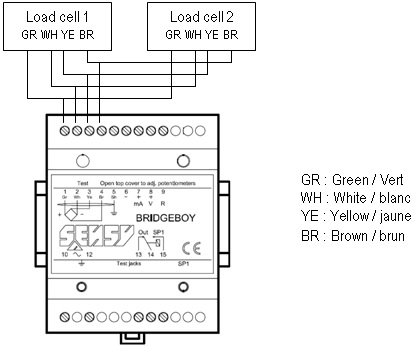
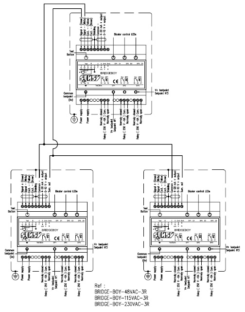
That is why we recommend the following schematics if you need to have a load limitation on the sum of the load of 2 load-cells.
CE certification is then available.
[meta_title] => [meta_description] => [meta_keywords] => [tags] => [link_rewrite] => technical-note-about-limitation-of-load-limiter-realized-with-2-load-cells-and-1-bridgeboy [link_rewrite_cat] => load-cells )[2] => Array ( [id_gomakoil_faq] => 4 [id_gomakoil_faq_category] => 2 [link_rewrite_no] => [most] => 0 [association] => 0 [hide_faq] => 0 [name] => Admin [email] => no [by_customer] => 0 [position] => 4 [active] => 1 [date_add] => 2019-05-17 03:21:05 [as_url] => 0 [id_lang] => 2 [id_shop] => 1 [question] =>
What is the maximum cable length available for an Exi certified sensor?
[answer] =>Answer:
It depends on the output signal of the sensor and values on the Exi certificate:
Example with our certificate ISSeP07ATEX012X:
- Non-amplified output (Wheatstone bridge – mV/V): Options I4 or I6
Our certificate ISSeP07ATEX012X specifies that:
- The capacitance of the cable may not exceed 14 nF
- The inductance of the cable may not exceed 10 µH
The capacitance of our standard cable (4 wires) is 130 pF / m, its inductance 0.7 µH / m. The maximum length is in this case 14 m because we then reach the maximum inductance.
2. Current output (4…20 mA – 2 wires) : Option C6
In this case, the same certificate specifies that:
- The capacitance of the cable may not exceed 53 nF
- The inductance of the cable may not exceed 150 µH
The capacitance of our standard cable (2 wires) is 150 pF / m, its inductance 0.65 µH /m. The maximum length is in this case 230 m because we then reach the maximum inductance
[meta_title] => [meta_description] => [meta_keywords] => [tags] => [link_rewrite] => What-is-the-maximum-cable-length-available [link_rewrite_cat] => load-cells )[3] => Array ( [id_gomakoil_faq] => 6 [id_gomakoil_faq_category] => 2 [link_rewrite_no] => [most] => 0 [association] => 0 [hide_faq] => 0 [name] => Admin [email] => no [by_customer] => 0 [position] => 5 [active] => 1 [date_add] => 2019-05-27 06:20:51 [as_url] => 0 [id_lang] => 2 [id_shop] => 1 [question] =>What is the required power supply for a sensor with integrated amplifier that provides a 4-20 mA (2-wires) signal?
[answer] =>Answer:
The particularity of the power supply for sensors equipped with a 4-20mA (2-wires) amplifier (Option C or C6) is that it depends on the value of the load resistance of the reading instrument (RL) increased by the resistance of the wiring (RW).
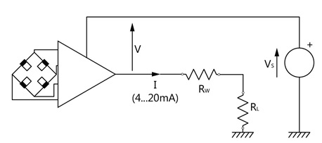
Indeed, for a correct operation, the power supplyat the terminals of the amplifier (V) must be at least 9 to 28VDC. However V = VS - I x (RL + RW) with I being able to reach 20 mA.
Consequently, Vs must be greater than or equal to 9 + (RL + RW) x 0.02.
Examples:
- Input resistance of the reading device RL: 33 Ohms Wiring resistance Rw: 4 Ohm. To be able to generate a 20mA signal, the supply voltage must be at least: 9V + ((33+4)*0.02) = 9.74V
2. With RL + RW = 1 kΩ (abnormally high value), VS must be at least: 9 + 20 = 29 V to be able to generate a 20mA signal with the specified linearity.
Likewise, for a specified supply voltage, the value of the sum of the load resistors will be limited to (VS - 9) / 0.02.
Example: With VS = 24 V, the value of RL + RW may not exceed 750 Ω in order to generate a 20mA signal with the specified linearity.
[meta_title] => [meta_description] => [meta_keywords] => [tags] => [link_rewrite] => What-is-the-required-power-supply-for-a-sensor [link_rewrite_cat] => load-cells )[4] => Array ( [id_gomakoil_faq] => 9 [id_gomakoil_faq_category] => 2 [link_rewrite_no] => [most] => 0 [association] => 0 [hide_faq] => 0 [name] => Admin [email] => no [by_customer] => 0 [position] => 6 [active] => 1 [date_add] => 2019-05-28 06:07:10 [as_url] => 0 [id_lang] => 2 [id_shop] => 1 [question] =>Can a load pin be used in both directions ?
[answer] =>Answer:
Our load pins are based on the strain gauge technology. Thus, they can be loaded in both directions.
This is especially true if the signal is not amplified (i.e., mV/V).
In the case of an amplified signal (4..20mA), it will be necessary to shift the zero signal; for example, to 12mA.
In addition, at the end of manufacturing of the usual one direction load pins, they are loaded at 200% of their nominal load in order to ensure perfect zero stabilization. This operation is not performed for load pins intended to be used in both directions.
Therefore, it is necessary to specify it when ordering so that we can take it into account during manufacturing.
Remark:
Since the output signal may be zero, this may be a problem for the detection of wire break or short circuit in the context of positive safety.
[meta_title] => [meta_description] => [meta_keywords] => [tags] => [link_rewrite] => Can-a-load-pin-be-used-in-both-directions [link_rewrite_cat] => load-cells )[5] => Array ( [id_gomakoil_faq] => 10 [id_gomakoil_faq_category] => 2 [link_rewrite_no] => [most] => 0 [association] => 0 [hide_faq] => 0 [name] => Admin [email] => no [by_customer] => 0 [position] => 7 [active] => 1 [date_add] => 2019-05-28 07:06:42 [as_url] => 0 [id_lang] => 2 [id_shop] => 1 [question] =>What different types of rope reeving systems are used for lifting equipment?
[answer] =>Answer:
A rope reeving is a mechanical device with several pulleys commonly used on lifting equipment. It allows to lift heavy loads while limiting the force applied on the hoisting ropes.
There are many different types of rope reeving. For each one, there are one or more optimal locations to mount the force sensor (s) (loadcell on the cable, load pin, tension or compression sensor, wedge socket) which will allow the limitation of hoisted load. The choice of the type of sensor and its location will be based according to criteria such as the required accuracy, the possibility of loss of lifting height, the cost of equipment and assembly, etc ...)
Some of the most common examples are shown below (non-exhaustive list).
![]() indicate where to mount the force sensors.
indicate where to mount the force sensors.


What is the maximum length of measurement cables ?
[answer] =>Answer:
The maximum length of the measurement cables depends on many parameters. Some are internal because they depend on the type of signal (analogue, digital, mV / V, 4 ... 20 mA, RS-232, USB, etc.); others are external such as the electromagnetic and thermal environments of the installation.
In practice, simple precautions will easily prevent some pitfalls:
- Do not route measurement cables near power cables
- Always use faradised (shielded) cable and connect the shield to the ground.
- Preferably, use twisted pairs.
- Adapt the wire section to the length of the wiring.
A. Analogue signals
There are mainly 3 types of analogue signals for strain gage sensors:
- Non-amplified signal (Wheatstone bridge - mV / V)
This type of signal is not normally intended to be transported over long distance. It will therefore be limited to a length of 20 m taking into account the environmental conditions mentioned hereabove.
The use of sense lines at the power supply level eliminates the effects of temperature on power cables.
A larger section of cable (eg: 0.5 mm² instead of 0.14 mm²) also makes it possible to limit voltage losses and their thermal drift.
- Amplified signal 4..20 mA
This kind of analogue signal is an industrial standard.
It has the advantage of not being sensitive to the length of the cable and therefore being able to transmit a signal over several hundred meters.
In addition, it can detect any cut wire because the signal cannot be zero.
It exists in 2 versions:
- 2 wires where the sensor supply is provided by the measuring loop
- 3 wires where the sensor supply is provided by a 3rd wire.
However, the sum of the voltages at the inputs of the reading devices and the available supply voltage must be considered.
- Amplified signal 0 ... 10V and -10..0..+ 10V
This type of signal has the advantage of being able to connect the reading devices in parallel and thus without interrupting the measurement loop as is the case of 4..20 mA. This is particularly useful during checks.
It also makes it possible to keep the zero at 0 V, which gives an image closer to the measured quantity, particularly in the case of bidirectional sensors (eg tension + compression).
Considering the precautions mentioned above, we recommend 50m as maximum length.
B. Digital signals
- RS-232
This kind of connection is not intended for long distances.
The maximum cable length depends on the transmission speed
For example, it will be limited to 5 m in the case of a transmission to 19 200 Baud.
- RS-485
This kind of connection makes it possible to transmit signals over greater distances:
In addition, it allows to connect several devices on the same bus.
The maximum cable length also depends on the transmission speed.
Typically, with the use of line matching resistors, a length of 1200m is allowed up to a transmission rate of 100 kbps.
This maximum value may be limited by equipment manufacturers.
- USB
The USB standard does not allow a cable longer than 5m.
Note: There are repeaters that can extend this length up to 15m.
[meta_title] => [meta_description] => [meta_keywords] => [tags] => [link_rewrite] => What-is-the-maximum-length-of-measurement-cables [link_rewrite_cat] => load-cells )[7] => Array ( [id_gomakoil_faq] => 35 [id_gomakoil_faq_category] => 2 [link_rewrite_no] => [most] => 0 [association] => 0 [hide_faq] => 0 [name] => Admin [email] => no [by_customer] => 0 [position] => 9 [active] => 1 [date_add] => 2019-07-02 08:28:23 [as_url] => 0 [id_lang] => 2 [id_shop] => 1 [question] =>Why is it necessary to connect SENSY electronics and sensors to protective earth ?
[answer] =>Answer:
Grounding consists in connecting to a protective earth point with a conductive wire a metal structure that may be accidentally brought into contact with the electrical power grid caused by an insulation issue.
The grounding allows leakage currents to flow safely, combined with an automatic disconnection device (differential circuit breaker), it will switch off the electrical installation.
Why grounding ?
For user’s safety !
Example:
Take a SENSY electronics that is not connected to a grounded power outlet and a rodent that damaged the outer sheath of the power cable from this unit and its wires touch the housing
Touching the enclosure while being on a conductive floor will cause electric shock
Grounding combined with differential circuit breaker prevents such an incident.
The current flows directly into the ground and the power supply is automatically shut off.
No more electrocution, no more danger !
All SENSY electronics and sensors must be grounded !!!
Grounding is only effective if it is associated with a differential circuit breaker.
A good protective earth connection must have an electrical resistance calculate on the sensitivity of the differential device of the installation. The maximum resistance of the protective earth connection must be 100 ohms.
Rules to follow:
- Protective earth connection must be away from any deposit or infiltration that may corrode it (e. g. chemicals)
- Grounding connection should never be submerged by water.
- Water, gas or heating pipes and metal cable sheaths must not be used as protective earth.
What is the fatigue resistance of SENSY load cells and torque sensors?
[answer] =>SENSY force and static torque transducers measure with strain gauge bridges the deformation of metal body caused by application of mechanical stresses.
This mechanical stress may not exceed the elastic limit of the material without damaging or destroying the sensor.
However, even with overloads within the elastic limit of the material, alteration of the proof body will occur if these overloads are applied repeatedly.
This deformation, which is initially very small, can ultimately lead to sensor failure.
This fatigue resistance is characterized by a guaranteed number of cycles. It depends on the material, the stress rate (μm/m) and whether this constraint is uni- or bidirectional.
For SENSY steel sensors, the fatigue strength is as follows:
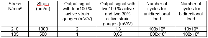
Caution: This is not valid for certain types of sensors for which the maximum stress is not located where the strain gauges are bonded.
(eg : membrane sensors).
[meta_title] => [meta_description] => [meta_keywords] => [tags] => [link_rewrite] => fatigue-resistance-of-sensy-load-cells-and-torque-sensors [link_rewrite_cat] => load-cells )) 1