
HOW DOES A LOAD PIN WORK ?
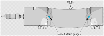
Load pin or “Clevis pin” or “dynamometric axle” is a shaft instrumented with a Wheatstone bridge for measuring double shear deformation. Some manufacturers design their load pin in a single shear for cost purposes, but at SENSY we do not believe in this solution as it generates greater uncertainties than the double shear design.
Load pin design obviously has the benefit of integrating itself in a system assuring the mechanical interface between the components and providing information on the applied forces. The most common examples are Clevis pins installed at the dead-end anchor point or upper sheave/equaliser beam of EOT cranes, used for suspending a chain hoist to its trolley, on a fairlead sheave of a winch, at the head of an hydraulic cylinder, for suspending lighting and other equipment in theatres or concert halls, etc.
The design principle relies on managing reduced load pin diameters at the areas of separation between the holding plates (flanges) and the central tool applying the main effort. The purpose of these reduced diameters is to create deformation zones where the strain gauges will be placed to ensure sufficient strain concentration that will guarantee accuracy and repeatability.
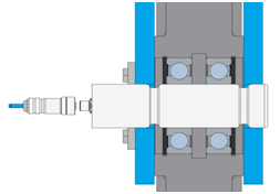
These reduced diameters determine the mechanical resistance of the load pin, which explains why a plain shaft sometimes cannot be replaced by a load pin because it requires oversizing the diameter. The high resistance quality of aeronautic-grade steels compensates for this mechanical modification.
The combination of load pin diameter, reduced diameters and size of strain gauge pockets to reach the pin’s neutral fibre to concentrate the necessary strain defines the safety coefficient of the clevis pin:
- “FORCE”: permissible overload: 150% of nominal capacity, breaking load >300%
- “HOIST”: permissible overload: 200%, breaking load >500%
- “LIFT” (lifting people or hanging equipment over people) : permissible overload: 400%, breaking load >1000%
Permissible overload means the maximum overload for which we guarantee no permanent deformation of the load pin (“0” offset).
Our design criteria are based on strain limitation on the different parts of the shaft (the most critical being those parts in contact with the holding plates that are generally thinner than the central tool). For “FORCE” load pins, we aim to remain in the 150-200N/mm² range; “HOIST” load pins are designed with strains limited to 100-120N/mm²; and strain of around 50N/mm² is the aim for the “LIFT” execution. If the operating span of the pin exceeds those strain values, we compensate the lack of span with an increased diameter.
These design criteria guarantee the load pin’s mechanical and fatigue resistance as well as the mechanical mounting equipped with the load pin. Having been in the overload protection business since 1991, we have load pins that have been in operation for more than 30 years. To understand the well-known safety factors, note that we use – in any case – aeronautic-grade steels with 1150 to 1350Mpa (or N/mm²).
Load pin accuracy depends on multiple factors. First, the ratio diameter/operating span (load pin supports and deformation zone) – if the load pin diameter is too close to the dimensions of its operating span, its accuracy performances will be dire (>3%). Good decoupling is vital: if the holding plates are in contact with the central tool (or sheave in hoisting applications) they will cause friction which will generate greater uncertainty, non-repeatability issues and, in extreme cases, the signal will not return to “0” because friction will not allow the releasing strains to be applied to the load pin (central tool/sheave will remain blocked in loaded position) – air gaps of a minimum 0.5-1mm between the flanges and the central tool are mandatory for good accuracy results.
A load pin is meant for operating in a one-effort direction. If a force is applied with an angle versus the operating direction, the output signal will be significantly reduced for any unchanged applied force as soon as the angle extends beyond 10°, and more if the angle increases. In the case of wire-rope wrapping around a sheave at 180°, the load pin operating direction will be oriented in the direction of both wire- rope falls; 90° wrap angle configuration implies that the load pin will be oriented at 45° between both wire-rope falls. We also manufacture double-direction load pins (X and Y) for those designs where force direction is constantly changing.
Clevis pin sensitivity (output signal) thus depends on pin diameter, reduced diameters and the span of the mechanical pieces holding the pin and applying forces to it. The “FORCE” design will generate about 1.5-2mV/V; ±1mV/V for the “HOIST” design; and around 0.5mV/V for the “LIFT” version. But, it also depends on the mounting for the load pin. Half-moon parts supporting the pin and applying forces to it will generate a specific sensitivity, while mounting that completely surrounds the pin diameter will generate another sensitivity. The hardness of material holding the pin and applying forces to it also influences load pin sensitivity, as does the span of the corresponding mounting.
By combining the mechanical mounting with the design and hardness of the material used, it becomes obvious that a sole live calibration on a live mounting is guaranteed to provide the true image of applied efforts with the corresponding output signal. Any laboratory calibration, even with a calibration tool which reproduces similar mounting conditions, will be more of a pre-calibration with its associated uncertainty than a calibration on a live mounting with actual forces.
In terms of dimensions, we produce load pins of minimal diameter 7mm and, in fact, no limitation in terms of maximum diameter; we have already manufactured a load pin with a diameter ranging from 360 to 480 mm. Nominal capacities between 2000N (0.2t) and 30MN (3000t) and even beyond can be produced on customer request and after careful analysis of the application. We commonly use external bonding of strain gauge design for most applications (model 5000-5300-5600 with visible pocket covers), keeping the internal bonding of strain gauges (design 5050) for submerged/subsea requirements (up to -5000m and more), high-pressure applications (up to 700bars) or ATEX Ex d (explosion-proof).
As regards our standard model (5300) or custom-made models (5000 and 5600), all these can be adapted to customer requirements, thanks to limitless options ranging from the special connector type to ATEX/IECEx/CSA (CA/US), through Ingress Protection IP65 to 68 and special cables, as well as a temperature compensation range from -50°C to +200°C (-58°F to +392°F) including a flameproof sleeve or hydraulic hose for protecting the cable.
As for output signals, beyond the standard mV/V output, load pins can be equipped with embedded amplifiers with the following signals: 4-20mA, 0-10V (and derived), RS485, Modbus and CAN. Analogical amplifiers can be calibrated with a span from “0” to nominal capacity or any other capacity, allowing overloads without signal saturation.