LOAD CELLS – PERFORMANCE LEVELS ACCORDING TO ISO 13849
What’s the standard ISO 13849 – "Safety of Machinery - Safety-related parts of control systems” ?
Our modern and industrialised world can no longer operate without machines. Whether they are used for heavy tasks or the most thorough, machines and automated systems are essential tools to reduce employees’ workloads while ensuring speed and quality of work.
As powerful as these tools are, they also present a significant danger for humans. This is how the principles of machine safety and machine directive were born.
The idea of different safety standards is to provide legal certainty for both the manufacturer and the user, the latter wishing to have access to a safe and efficient machine.
Using this approach, all machine manufacturers must make risk assessments in order to eliminate or reduce them according to requirements. This is very important when we refer to the features of safety itself.
One of the most commonly used safety standards is ISO 13849 – "Safety of Machinery - Safety-related parts of control systems’. This standard gives valuable information on producing a control system.
SENSY, as a partner in your process of creating and securing your machines, offers solutions for producing PL-compliant installations up to PLe.
Within this perspective, this article offers a summary of the main concepts to keep in mind when carrying out a security order.
Determine your required ‘PL’
ISO 13849 provides different safety levels for machines. These performance levels (PL) are represented by a letter from "a" to "e", with "PLa" being the lowest level and "PLe" the highest.
The requirements for developing systems at different levels can vary greatly in cost. Thus, it is important to choose the PL level your installation needs.
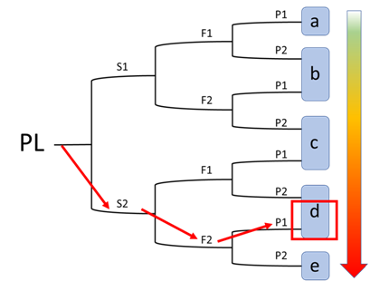
Determination of the required PL level depends on three variables: the severity of the injuries, the exposure frequency to the hazard, and the probability of avoiding the danger or limiting the damages.
There are two severity levels:
S (severity)
- S1 = minor injuries (normally reversible)
- S2 = serious injuries (irreversible, including death)
F (frequency of exposure to danger)
- F1 = rare exposure or exposure of short duration
- F2 = frequent or continuous exposure
P (probability of avoiding danger or limiting damages)
- P1 = possible under certain conditions
- P2 = rarely possible or impossible
Safety function design
The creation of a system providing a safety function requires the estimation of several factors:
- The architecture of different hardware and software (categories);
- Possible diagnostic coverage;
- Component reliability (MTTFd);
- Common causes of failure.
Categories
CAT B
- I : Input
- L : Logic
- O : Output
- Ic : inter-connections
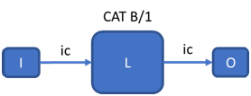
This is the simplest architecture. It includes a single signal sensor on a programmed logic that will provide a single signal/command output. This architecture is the least secure and any failure or defect will result in a possible total loss of safety function.
In the case of category B architectures, the MTTFd of the components is less than 30 years with a minimum of three years.
CAT 1
- I : Input
- L : Logic
- O : Output
- Ic : inter-connections
The architecture is identical to category B BUT the MTTFd of the components must be at least 30 years. It should also be noted that ISO 13849 provides a maximal MTTFd of 100 years to be taken into consideration. After that, the MTTFd on the PL is reached. This is because safety should never be based only on reliability.
The only difference between category B and category 1 is a higher MTTFd.
CAT 2
- I : Input
- L : Logic
- O : Output
- TO : Test Output
- m : Monitoring
- Ic : inter-connections
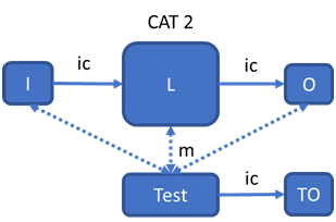
This architecture includes a single signal sensor on a programmed logic that will provide a single signal/command output. From category 2, the system must satisfy minimum diagnostic coverage of the various potential faults.
Thus, this architecture includes a test system. This is carried out when the machine starts or in a timely manner and must cover at least 60% of failures.
Note that under this architecture a loss of function is possible between two periodic tests.
CAT 3
- I : Input
- L : Logic
- O : Output
- m : Monitoring
- cm : cross-monitoring
- Ic : inter-connections
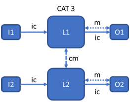
This architecture includes a dual signal sensor or two sensors on a programmed logic that will provide two output signals/commands. Thus, this architecture includes a test system which carries out the tests continuously and will have to cover at least 60% of the failures.
In the event of a single fault, the safety function must be ensured. An accumulation of faults can lead to a loss of safety function.
CAT 4
- I : Input
- L : Logic
- O : Output
- m : Monitoring
- cm : cross-monitoring
- Ic : inter-connections
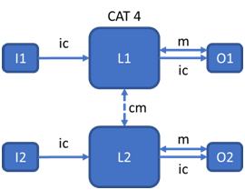
Almost all dangerous faults must be detected by a continuous test (DC 99%). The safety functions are ensured even in the case of multiple faults. Consequently, faults must be detected before loss of safety function.
Diagnostic coverage
The diagnostic coverage is the value that quantifies the system's ability to diagnose dangerous faults. This value is expressed as a percentage.
For example, the diagnostic coverage of a relay fault can be assessed. If a N / O relay were to close on an open circuit, the system would not necessarily be able to differentiate between the fault and the conventional opening. A highly diagnostic system will include systems which enable the state of the relay to be checked.
It is obvious that the system’s architecture has a direct link to the diagnostic coverage of the latter. Any system having to justify PLs corresponding to categories 2 and 3 will have to justify 60% DC or even more (see table PL-Cat-DC-MTTF).
It is also important to note that some architectures are not appropriate for justifying the DC of some systems. Thus, a category 2 system is readily suitable for a simple detection system (i.e. mechanical stops) which can easily be tested during activation of the machine. However, the reliability of more complex systems would be very bad. These systems may require extremely complicated test systems. Therefore, it is often easier and more economical to test a system with a redundant architecture.
Component reliability (MTTFd)
The reliability of components is obviously at the heart of a system's ability to perform its security function. The lower the component’s reliability, the more likely it is to cause failures (and thus dangerous failures).
Note, however, that it would be wrong to consider a component’s reliability as the sole justification for achieving high performance levels. ISO 13849 also provides a limit on the use of an MTTFd (100 years) because an MTTFd value is an average and does not reflect reality. It is therefore likely that a reliable product will fail, despite a small statistical probability. This is especially true in case of failure because this component will not be immediately identified as the probable cause of it.
Common causes of failure
The common causes of failure must be considered for systems from category 3 and above. Indeed, in these systems, the possible causes of a failure may affect several of the system’s elements (i.e. both channels can be overloaded at the same time!).
The causes of common failures can be estimated on the basis of annex D of EN 61508. It is obvious that common failures only occur in the presence of a system with two input and/or output signals.
The common failure rate is given in percentage.
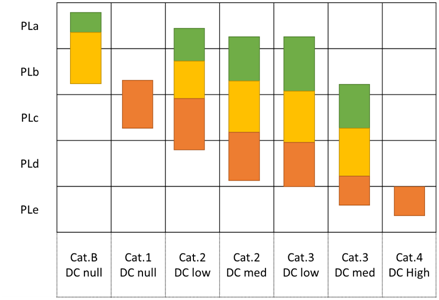
Determining if the PL level has been reached
All these factors make it possible to determine the achieved level. A quick glance at the table below shows the influence of these factors:
 MTTFd low: 3 ≤ MTTFd < 10 years
 MTTFd medium: 10 ≤ MTTFd < 30 years
 MTTFd high: 30 ≤ MTTFd < 100 years
MTTFd results above 100 years are automatically considered as 100 years from the normative point of view.
Example: determination of a reached PL level
Since an example is often more meaningful than a long explanation, we will take a brief look at a small case concerning concrete: an EOT crane in an industrial application.
The latter is in a workshop where a small group of technicians work.
The area of EOT crane use is well defined and the bridge man has been duly trained. The procedure for using the crane requests that a safe distance is respected and that no one goes under the load. Note that the crane is only used for lifting heavy metal parts (engines, shafts, etc.).
After a risk assessment by the safety officer, the various points relating to determination of the PL level were noted: in this case, the safety officer determined that the injuries caused by a crane accident would be serious (S2), the exposure is frequent (F2) although the probability of avoidance is important (P1).
By using the diagram below, it can be seen that the PLd level is required.