


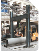


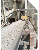


When rules on load limitation of hoisting equipment above 1-tonne capacity were introduced, many corporations using high-capacity EOT cranes, mainly in the steel manufacturing industry, argued that a hot steel ladle cannot contain more hot steel than its volume allows and that the corresponding load is known rather than variable. For many years, this has been accepted by inspection agencies issuing derogations with this justification authorising the practice of not having overload protection devices on the cranes concerned as the loads to be lifted could not be higher than they actually are.
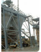
Overhead cranes in power-generator halls within nuclear, thermal, hydraulic or hydroelectric power plants followed the same reasoning: the weight of the rotors to be removed periodically for refurbishment, as well as the refurbishment of corresponding stators, is known (specified by the manufacturer) and the capacities of the cranes have been sized accordingly. This is also applicable to overhead cranes for tools forming presses of body pieces in the cars/industrial vehicles industry.
What has been accepted for decades is no longer so as risk assessments now consider the potential risk of accidents in relation to the load being hooked to the structure of the surrounding hall or vehicle, office container or tooling in the path of the load during lifting, lowering, long-travel or short-travel movements. As the cranes are usually optimised for their operating scope of work, any accidental blocking of the load may lead to dynamic overload which, in the worst case scenario, can result in hot steel being poured out, load drop, wire rope rupture with dramatic human and material damage, the permanent deformation of structures, etc. The same applies for a rotor on a power unit or a tool in a press that remains blocked while an attempt is made to lift it.
In order to prevent such incident/accident, it has become mandatory to instal overload protection devices in those countries which have implemented this regulation in their laws and strongly advised in those countries where no such safety regulation applies – so far.
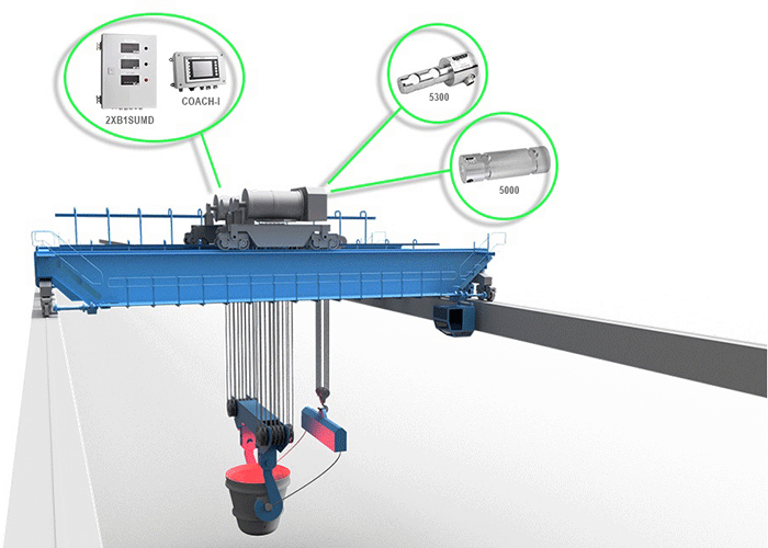
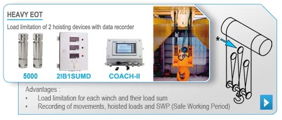
Such heavy hoisting systems are generally equipped with auxiliary hoists which, if their capacity is not as high as the main hoists, the combined loads of both main and auxiliary hoists may exceed the nominal capacity of the EOT crane. For this reason, in addition to the individual overload protection device, a summing module will also be necessary. Each load limiter will protect its corresponding hoist against overload, while the summing module will receive load informations from the individual limiters analog outputs to ensure the overload protection of combined loads.
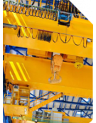
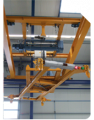
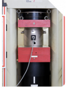
This type of heavy EOT crane is usually made from rope reeving with 16 to 24 wire rope falls, two drums and dead-end anchor points on balancing beams or tie beams going through the frame of the trolley, either with one or multiple upper sheaves.
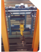
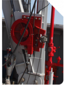
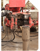
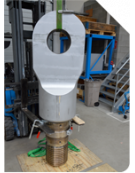
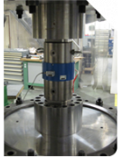
For dead-ends on balancing beams, force information is obtained through the load pin; for tie beam anchoring, it is either the load pin between the tie beam and wire rope socket or annular load cell between the trolley frame and the locking nut of the tie beam. In the absence of anchor points (rope passing from one drum to the other), there will be an upper sheave or a group of sheaves on to which the load pin can be installed.
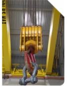
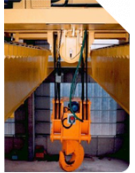
How many dead-ends should be equipped with force sensors? This will depend on what is suspended on the wire rope falls. If it is a sole hook block, just one load cell will suffice for the required overload protection; if it is a spreader leading to a potentially unbalanced load between the hooking points, it will be necessary to equip each anchor point with a transducer to allow for the discrimination of loads at either side of the spreader. For such a spreader mounting, the operators can either use one load limiter per dead-end or an intelligent junction box that will monitor the anchor points individually, including unbalanced loading and one load limiter to ensure overload protection of the hoist, as well as slack rope detection, if required. A power relay from the junction box will be linked in serial with the load limiter’s overload relay to cut out the lifting movement if a load unbalances, as well as if one sensor signal is faulty (overload, damaged cable, etc.).
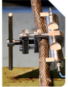
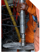
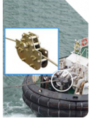
Load cells often used for this type of application


Electronics often used for this type of application


